PHOTORESIST
Positive, Negative and Image Reversal Resists
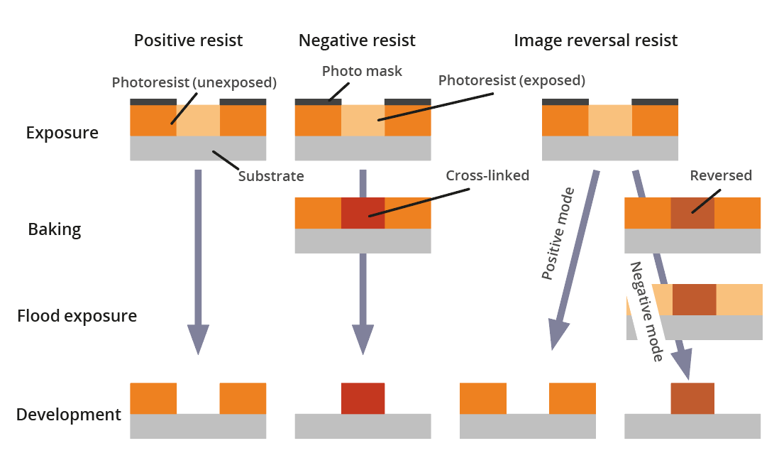
Positive resists form an indene carboxylic acid during exposure making them soluble in aqueous alkaline solutions. Therefore, positive resists develop where they have been exposed, while the unexposed areas remain on the substrate. Since positive resists do not cross-link, the resist structures rounden beyond their softening point of typically 100-130°C.
Negative resists such as the AZ® nLOF 2000 series or the AZ® 15nXT or 125nXT cross-link after exposure and (not required for the AZ® 125nXT) a subsequent baking step, while the unexposed part of the resist is dissolved in the developer. The crosslinking makes the resist thermally stable, so even elevated temperatures will not deteriorate the resist profile. However, towards higher and higher process temperatures, the degree of crosslinking increases and it becomes hard or even impossible to wet-chemically remove the resist.
Image reversal resists can either be processed in positive or negative mode. In the positive mode, the process sequence is the same as for positive resists. In the image reversal mode, an image reversal bake after the exposure followed by a flood exposure without mask is required. Even in the negative mode, the degree of crosslinking of the resist is rather low, so the resist structures will rounden beyond the softening point of typically 130°C.

Resist Coating Techniques
Spin-coating is the most common coating technique for resists. Almost all AZ® and TI resists are optimized for spin-coating and allow very smooth and homogeneous resist films. The attained resist film thickness goes with the reciprocal square root of the spin speed and thus is adjustable in a certain range for each resist. However, since the edge bead becomes more pronounced towards low spin speeds, for attaining thick films we recommend to use highly viscous resists such as the AZ® 4562 or AZ® 10XT, as well as suited spin profiles.
Spray coating allows the coating of almost arbitrary shaped and textured substrates. In order to attain a smooth and homogeneous resist film thickness as well as a good edge coverage of textures (if existing), an optimized resist composition with different solvents with low and high boiling points is required. The spray coating resists AZ® 4999 and TI Spray meet these requirements for almost all spray coating applications.
Dip coating is a suited coating technique for large, rectangular shaped substrates and the demand for a minimum resist consumption per coated area. For a homogeneous resist film thickness over the entire substrate, a certain solvent composition in the resist is required as realized in the MC Dip Coating Resist.
Fields of Application of the Resist Mask
Wet chemical etching requires an optimized adhesion to the substrate. For this purpose, we recommend the AZ® 1500 series for resist film thicknesses of 500 nm to 3 µm, the AZ® ECI 3000 series for 1-4 µm resist film thickness, or the AZ® 4500 series for films of several 10 µm thickness. In case of low resolution requirements, the PL 177 is a economically priced alternative. HF-containing etchants sometimes cause large-scale resist peeling as a consequence of HF-diffusion through the resist towards the substrate underneath. In this case, it’s generally beneficial to increase the resist film thickness using resists such as the AZ® 4562 or the AZ® 10XT.
Dry etching requires an elevated softening point of the resist as well as steep sidewalls. The high-resolution AZ® 701 MIR 14CPS or 29CPS, are optimized for both requirements and reveal a softening point of 130°C.
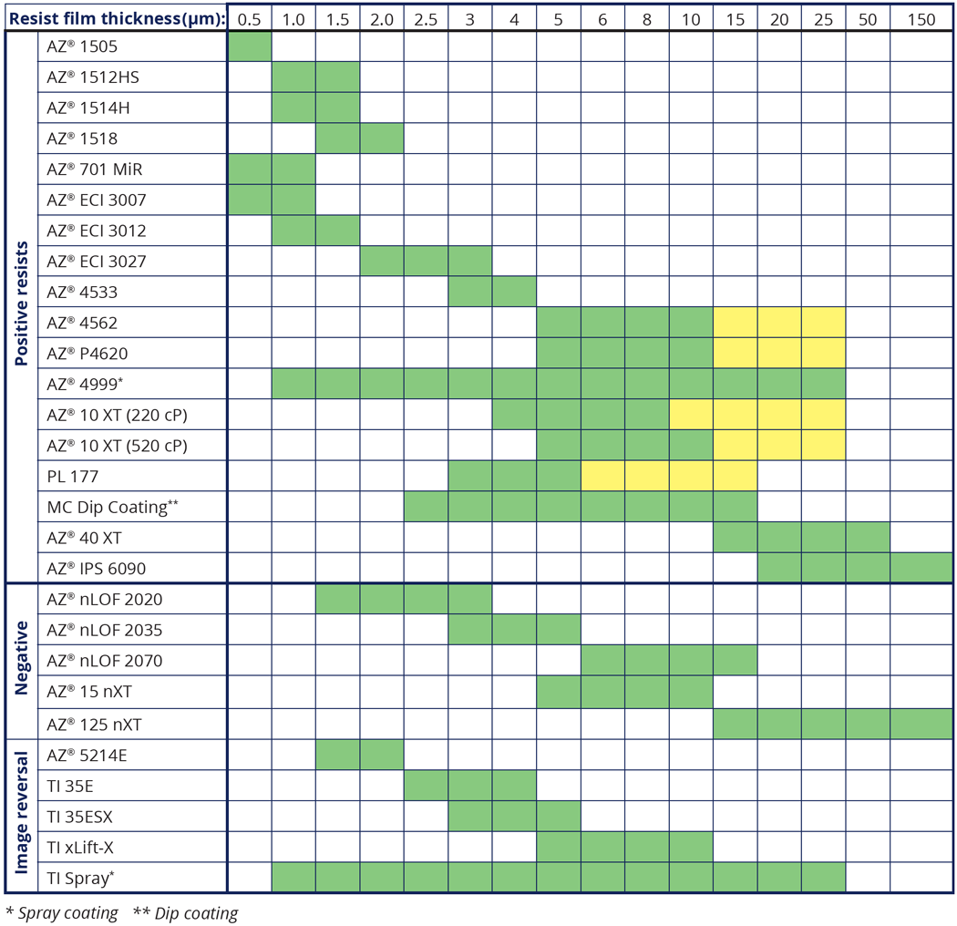
Thick resists: If resist film thicknesses exceeding 5 µm are required, the thick positive resists AZ® 4562 or AZ® 10XT, or the negative AZ® 15nXT or AZ® 125nXT are recommended. The two nXT resists cross-link and therefore reveal an excellent thermal stability during dry etching.
Lift-off processes recommend an undercut resist profile which can be attained with image reversal resists such as the AZ® 5214E (resist film thickness 1-2 µm), the TI 35ESx (3-5 µm), or the AZ® nLOF 2000 (2-20 µm) negative resists.
Additionally, these resists are thermally stable and therefore help to
prevent a rounding of the resist structures during coating.
If the
mask design requires positive resists for lift-off application, the
resist sidewalls should be as steep as possible in order to prevent a
coating of these sidewalls. For this purpose, we recommend the
high-resolution resist AZ® 701 MIR 14CPS or 29CPS.
Electroplating requires an improved adhesion of the resist to the substrate as well as an enhanced stability of the resist in the electrolyte. The negative resists AZ® 15nXT (resist film thickness 5-30 µm) and AZ® 125nXT (up to approx. 150 µm) are optimized for these requirements. Both resists can be developed in TMAH-based developers, wet-chemically stripped in common removers, and are compatible with all common substrate materials and electrolytes for Cu-, Au-, and NiFe plating. If positive resists have to be used for electroplating, the AZ® 4500 series and the AZ® 10XT allow steep sidewalls and a good adhesion.

Attainable Resist Film Thicknesses
Generally, the last two digits of the resist name indicate the film thickness attained by spin coating (without gyrset) at 4000 rpm in 100 nm units. The thickness approximately decreases with the (increasing) square-root of the spin speed, so a given resist allows a certain range in the attainable resist film thickness. If the desired resist film thickness can/should not be realized by varying the spin speed, the usage of a different available viscosity of the given resist is recommended. Otherwise, the following has to be considered:
Dilution of high-viscosity resists with PGMEA (= AZ® EBR Solvent) allows to perform several applications with different film thicknesses using only one resist. However, diluted resists are sensitive to particle formation with a reduced expiry date depending on the resist, the dilution ratio and the storage temperature and -time for the diluted resist. Since the particles partially consist of the photo active compound, a particle filtration before usage increases the dark erosion and decreases the development rate of the resist. For information on specific dilution recipes please contact us.
Realizing thick films with low-viscosity resists is problematic for two main reasons: i) The required low spin speeds increase the edge bead, and ii) in case of positive or image reversal resists, the rather high concentration of the photo active compound (low optical transparency) in typical 'thin resists' requires high exposure doses for a sufficient exposure, which makes steep resist profiles hard to realize and may cause popping and foaming by N2-bubbles formed during exposure.
Lateral Resolution and Aspect Ratio
The photoresist itself as well as the resist film thickness limit the theoretical resolution. Under optimum conditions, high-resolution thin resists such as the AZ® 701 MIR allow feature sizes of approx. 300 nm using i-line exposure.Beside a high absolute resolution, some processes require a high aspect ratio (ratio of the feature height to their width). Modern thick resists such as the AZ® 10XT allow an aspect ratio of 6-10, and even higher values under optimized process conditions.In many cases not the resist, but the equipment and process parameters limit the attainable resolution. In order to maximize the resolution of a given resist, besides the exposure conditions (no gap between mask and resist caused by particles, bubbles, or an edge bead), also the softbake parameters, the exposure dose, and the development (developer and its concentration, development time) have carefully to be optimized.
Spectral Sensitivity
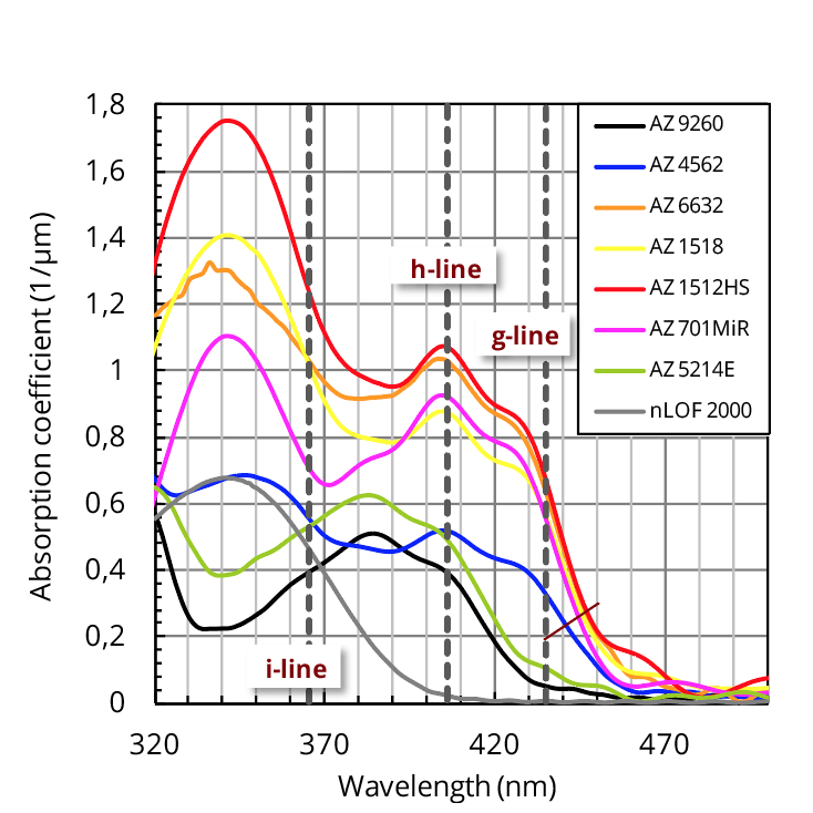
The optical absorption (fig. right-hand) of unexposed positive photoresists ranges from approx. 460 nm in the VIS to near UV, which is matched to the emission spectrum of Hg lamps in mask aligners. This absorption spectrum causes the typical reddish-brownish colour of many photoresists. During exposure, photoresists almost completely bleach down to approx. 310 nm. Some modern positive resists such as the AZ® 5214E or AZ® 10XT are not sensitive at g-line, while most negative resists such as the AZ® nLOF 2000 series, or the AZ® 15nXT and 125nXT are only sensitive near i-line and therefore appear almost uncoloured to the human eye.The optical absorption range does not end abruptly towards higher wavelengths. Therefore, high illumination intensity (e. g. laser scribing) or -times allow an exposure also some 10 nm towards the visible part of the spectrum. Some resists such as the PL 177, MC PC20 or AZ® 520D are dyed which makes it more easy to inspect the coating result.

Photoresist positive, thick |
| AZ® 10XT (220CPS) Photoresist |
| AZ® 10XT (520CPS) Photoresist |
| AZ® 12XT-20PL-10 Photoresist |
| AZ® 12XT-20PL-15 Photoresist |
| AZ® 3DT-102M-15 Photoresist |
| AZ® 40XT Photoresist |
| AZ® 4533 Photoresist |
| AZ® 4562 Photoresist |
| AZ® 4999 Photoresist |
| AZ® IPS-6090 Photoresist |
| AZ® P4110 Photoresist |
| AZ® P4620 Photoresist |
| AZ® P4903 Photoresist |
| AZ® PL177 Photoresist |
Dip Coating |
| MC Dip Coating |
P. Circuit Board Resist |
| AZ® PL177 Photoresist |
Antireflective Coating |
| AZ® Aquatar-VIII-A45 |
| AZ® Barli II 200 |
|
AZ® Barli II 90
|
Protective Coating |
|
AZ® P4K-AP Coating |
Photoresist negative |
| AZ® 125nXT-10B Photoresist |
| AZ® 15nXT (115CPS) Photoresist |
| AZ® 15nXT (450CPS) Photoresist |
| AZ® LNR-003 Photoresist |
| AZ® LNR-003 Photoresist dil. |
| AZ® nLOF2020 Photoresist |
| AZ® nLOF2035 Photoresist |
| AZ® nLOF2070 Photoresist |
| AZ® nLOF 2070 Photoresist dil.
|
| AZ® nLOF 5510 Photoresist |
Image Reversal Resist |
| AZ® 5209-E Photoresist |
| AZ® 5214-E Photoresist |
| TI Spray |
| TI xLIFT-X |
| TI 35 E |
| TI 35 ESX |
Spray Coating |
| AZ® 4999 Photoresist |
|
TI Spray |
Resist for Electroplating |
| AZ® 15nXT (115CPS) Photoresist |
| AZ® 15nXT (450CPS) Photoresist |
|
AZ® 125nXT-10B Photoresist |
|
AZ® 40XT-11D Photoresist |
|
AZ® 10XT (220CPS) Photoresist |
|
AZ® 10XT (520CPS) Photoresist |
|
AZ® IPS-6090 Photoresist |
Resist for E-Beam |
| AZ® nLOF2070 Photoresist dil. |
Resist for Lift-Off |
| AZ® nLOF2020 Photoresist |
| AZ® nLOF 2035 Photoresist |
|
AZ® nLOF 2070 Photoresist
|
|
AZ® 5215-E Photoresist |
| TI 35 ESX
|
Filter products


